How to Diagnose Combi-Oven Steam and Water-System Faults
Aug 27th 2026
Reading Time: 4 Minutes
Summary
Combi-oven steam faults may appear as fill or heating error codes, weak steam production, insufficient cavity humidity, water pooling, or steam-mode lockouts. Component layouts and operating sequences vary significantly by manufacturer and model.
To reduce unnecessary parts replacement and minimize equipment downtime, technicians should:
- Verify the exact water-system architecture (steam generator or boilerless) using the model-specific service manual.
- Isolate external factors such as incoming water pressure, drain restrictions, and water quality before testing internal components.
- Systematically test level sensors, inlet valves, heat-source outputs, and safety circuits before concluding that an electronic control board has failed.
Understanding Combi-Oven Steam Architectures
Most combi ovens generate steam through either a dedicated steam generator or a boilerless injection system. Before troubleshooting, identify the equipment’s architecture and retrieve the service information for the exact model and serial number.
| System Type | How It Works | Components May Include | Common Failure Points |
|---|---|---|---|
| Boiler-Based (Steam Generator) | A dedicated tank fills to a controlled level and heats the water as required. Steam is routed into the cooking cavity through a steam connection. | Conductivity probes or float sensors, heating elements or gas burners, drain valves or pumps, temperature limits, and automatic rinse systems. | Scale-coated conductivity probes, jammed drain valves, tripped high limits, ignition faults, or failed heating elements. |
| Boilerless (Direct-Injection/Flash-Steam) | Water is metered into the cooking cavity or onto a heated surface, where it rapidly vaporizes. The circulation fan distributes heat and moisture. | Injection valves, flow meters, cavity temperature and humidity sensors, circulation fans, and drain-quench systems. | Leaking injection valves, restricted nozzles, fan-distribution problems, inadequate cavity heat, or water-flow problems. |
Boilerless-system faults may involve the injection valve, cavity temperature sensor, humidity or climate-control sensor, water-flow monitoring, fan operation, or heat-source performance, depending on the model.
Primary Root Causes of Combi Steam Faults
Water Supply, Flow & Pressure Problems
Combi ovens require adequate flow volume and specific dynamic water pressure. A partially clogged external sediment filter, an undersized supply line, or an improperly adjusted pressure regulator can cause fill timeouts or poor steam production. That's especially true when multiple pieces of water-using equipment are operating simultaneously.
Water-Level Sensor Scaling
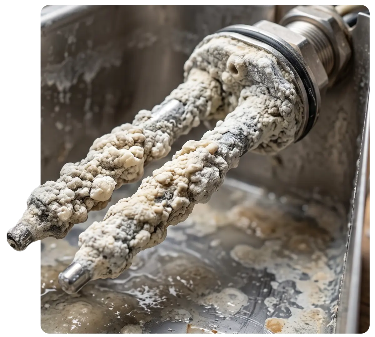
Scale coating a conductivity probe can prevent the control from detecting water, causing extended fill attempts or a fill timeout. Conductive contamination or damaged insulation may also produce an incorrect level signal.
The resulting behavior depends on the control design and safety sequence, so technicians should verify the probe circuit using the manufacturer’s service procedure.
Injection, Drain & Airflow Problems
In boilerless systems, a restricted nozzle, leaking injection valve, insufficient water flow, or inadequate cavity heat can prevent injected water from vaporizing correctly. Drain restrictions, quench-system malfunctions, fan problems, and damaged air baffles may also cause water pooling or improper cavity-moisture distribution.
Heat-Source & Output-Control Failures
Steam generation depends on sufficient heat input. Failures in the heat-delivery system may include:
- Electric units: Open heating elements, tripped high limits, or failed contactors and solid-state relays.
- Gas units: Ignition or burner lockouts, inadequate gas pressure, flame-sensing faults, combustion-air restrictions, or venting problems.
⚠️ Safety & Energy-Control Boundary
Steam generators, water lines, and drain components may retain hot water, steam, thermal energy, or pressure after shutdown. Follow the manufacturer’s shutdown and cooling procedure, isolate applicable electrical, gas, and water sources, allow components to reach a safe temperature, and verify that stored energy has been relieved before opening the system.
Temporary energization for testing must follow the employer’s established energy-control procedure under OSHA 29 CFR 1910.147. Live-voltage diagnostics must be conducted only by qualified technicians using properly rated test equipment and appropriate PPE.

Field Diagnostic Protocol
When troubleshooting a steam-generation fault, avoid jumping straight to component replacement. Follow a systematic approach using the service manual for the exact model and serial number.
1. Initial Assessment & Documentation
- Record the complete error code and the operating mode in which the fault occurs: initial fill, heat-up, steam production, drain, or cleaning.
- Confirm the model, serial number, voltage, and gas or electric configuration.
- Retrieve the correct service manual and wiring diagram.
- Check the equipment’s service history and event logs, when available.
2. Water Supply & Valve Checks
Dynamic Pressure: Measure incoming dynamic water pressure while the unit is actively calling for fill. Confirm that shutoff valves are open, supply lines are unobstructed, and external filters are clear.
Inlet Valves: On models with separate cooking-water and drain-quench connections, determine which circuit is affected before testing the valve. Verify that the valve receives its rated voltage during a fill call.
If voltage is present but water flow is insufficient, inspect the valve, strainers, and supply circuit according to the manufacturer’s procedure. If voltage is absent, verify wiring, interlocks, sensor inputs, and control outputs before concluding that the board has failed.
3. Level-Sensor & Injection-System Checks
Steam-Generator Models: Following lockout/tagout and the manufacturer’s cooling and draining procedure, inspect conductivity probes, float sensors, insulators, wiring, and connections for scale, contamination, damage, or grounding faults. Test the sensing circuit according to the manufacturer’s service procedure.
Boilerless Models: Inspect the injection nozzle, valve, water line, and any strainers or flow-monitoring components for restrictions, leakage, or damage. Confirm that the injection command, water delivery, cavity heat, and fan operation occur in the proper sequence.
4. Heat-Source Diagnostics
Electric Elements: Compare element resistance and phase current draw with the manufacturer’s service data. Test for leakage to ground using the specified method. Confirm rated voltage and total power using the equipment data plate.
Contactors & SSRs: Inspect contactors for burned or pitted contacts and verify the connected load before replacement. Replace an SSR only after confirming its control input, line voltage, output behavior, wiring, and connected load according to the service procedure.
Gas Systems: Qualified gas-equipment technicians should verify inlet and manifold pressure, inspect for ignition lockouts, and compare flame-sensor current with manufacturer specifications. Follow the manufacturer’s combustion-testing procedure and all applicable codes when diagnosing burner, combustion-air, or venting problems.
5. Drain, Vent & Sealing Checks
Before concluding that an injection valve or control board has failed because of poor cavity moisture:
- Inspect for a restricted cavity drain or blocked vent.
- Verify that the door gasket seals properly and the door latch is correctly aligned.
- Check for quench-system malfunctions.
- Inspect the circulation fan and air baffles for conditions that could disrupt heat and moisture distribution.
Before replacing a control board: Confirm water supply, valve operation, sensor inputs, heat-source output, safety circuits, wiring, and board power. An error code identifies the system that failed to complete an expected sequence; it does not automatically identify the failed component.
Frequently Asked Questions
What causes water to pour into the oven cavity during a steam cycle?
In a boilerless unit, water entering faster than it can vaporize may indicate a leaking injection valve, restricted or damaged nozzle, inadequate cavity heat, improper water pressure, or a fan-distribution problem.
In boiler-based equipment, it may indicate that the steam generator is overfilling because of a scaled conductivity probe or stuck-open water inlet valve. The exact route and symptom depend on the equipment’s design.
Can water-quality issues cause error codes on a combi steamer?
Yes. Water outside the manufacturer’s specified limits, including hardness, alkalinity, chloride, silica, TDS, or conductivity, depending on the specification, can contribute to scale, corrosion, sensor errors, and restricted water flow.
Compare water-test results with the requirements for the specific model before selecting filtration or treatment equipment.
Why does a combi oven work in convection mode but fail in steam mode?
Convection mode relies on dry heat and cavity fan circulation. Combi and steam modes require active moisture management, which may involve inlet valves, level sensors, injection components, a dedicated steam-generator heat source, and additional climate-control inputs.
A failure in the water, sensing, heating, or injection system may allow the oven to operate in dry convection while locking out steam-assisted modes.
Streamline Combi-Oven Repairs
For eligible applications, properly cross-referenced Original Component Manufacturer (OCM) parts may provide a cost-effective replacement option. Confirm compatibility using the complete model and serial number.
Verify all applicable electrical, water-flow, pressure, dimensional, temperature, and regulatory requirements—including coil voltage, frequency, contact configuration, and valve port sizing, as applicable—before ordering.
Use the AllPoints Parts Catalog and Technical Resources to cross-reference compatible valves, level sensors, heating components, and controls by equipment model and serial number. Accurate identification and systematic testing help reduce unnecessary parts replacement and keep combi-oven downtime to a minimum.