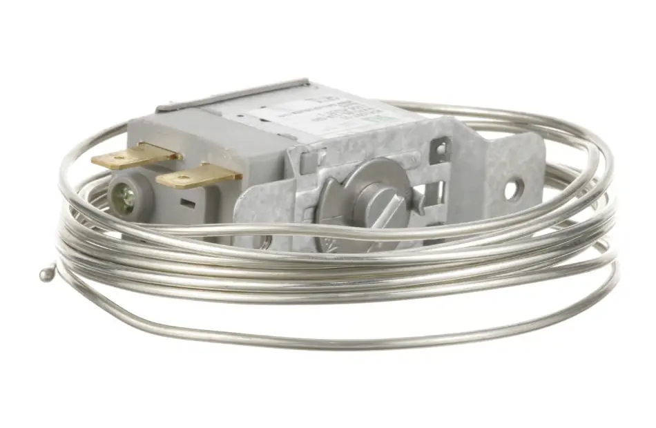
Walk-In Cooler and Freezer Defrost Failure: Diagnosing Timers, Heaters, and Termination Thermostats
Oct 19th 2026
Reading Time: 8 Minutes
Summary
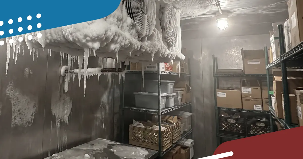
Frost buildup on commercial walk-in evaporator coils can restrict airflow, reduce cooling performance, and cause repeated service calls. While refrigerant issues and airflow restrictions can produce similar symptoms, failed defrost timers, heaters, and temperature controls are common causes of persistent ice accumulation.
Technicians can narrow down the cause by:
- Identifying the equipment's defrost method and control sequence.
- Verifying timer or electronic controller operation.
- Testing electric defrost heaters and drain-line heating components.
- Checking defrost termination and fan-delay controls against manufacturer specifications.
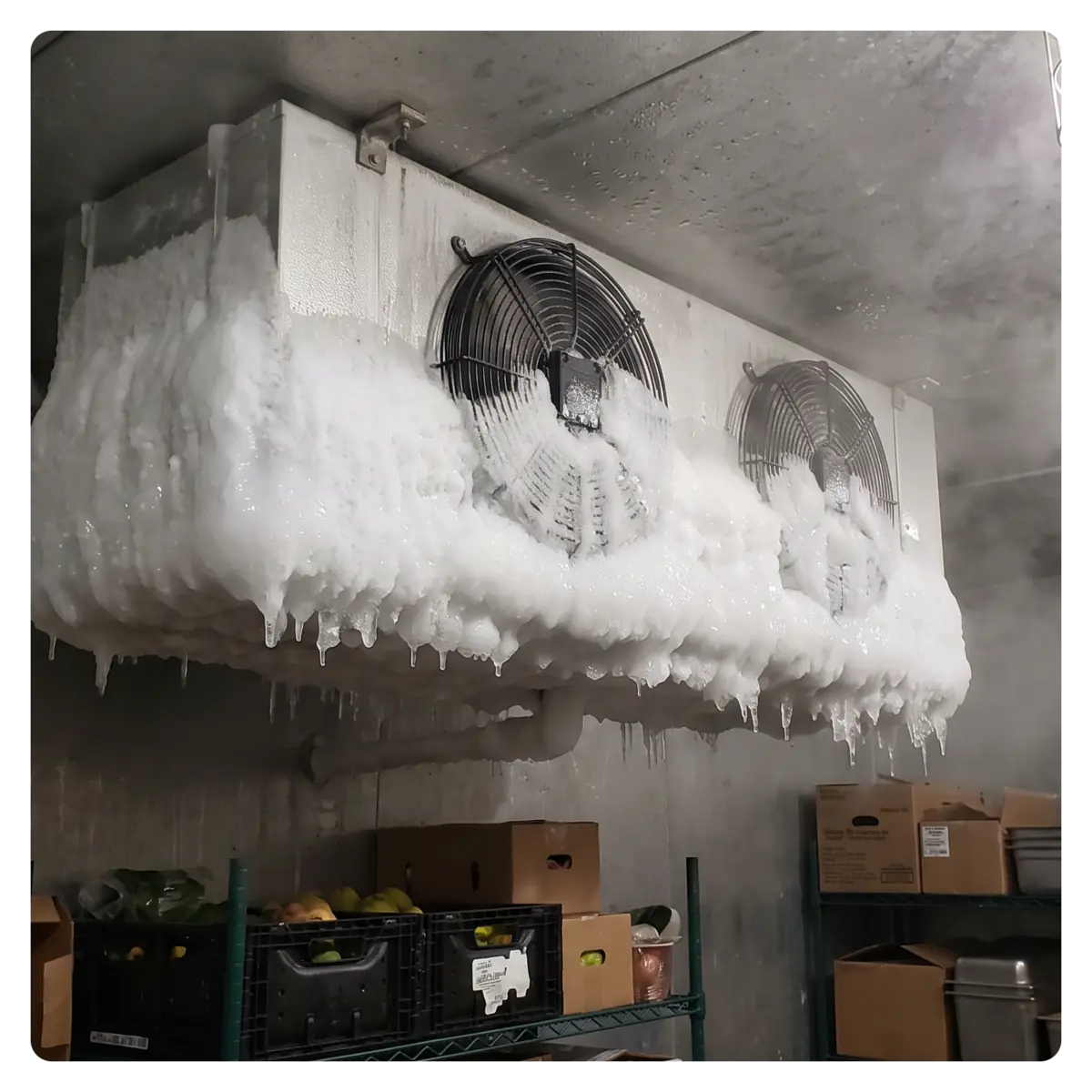
When a commercial walk-in cooler or freezer suffers a sudden temperature spike, a solid block of ice encasing the evaporator coil is often the first symptom a service technician encounters. The natural initial instinct in the field is frequently to suspect a low refrigerant charge or an expansion valve failure. Yet in commercial foodservice refrigeration, restricted coil airflow and persistent ice buildup far more commonly stem from a failure within the defrost system itself.
Walk-in evaporators operate below freezing temperatures during active cooling cycles, meaning moisture drawn from food product and humid ambient air entering through door openings constantly forms frost across the fin pack. To prevent this frost from choking off airflow and shutting down heat transfer, commercial systems rely on automated defrost cycles to clear the coil before returning to refrigeration.
When any single link in that defrost control chain breaks down, frost quickly compounds into impenetrable ice. Successfully restoring box temperature without repeat callbacks requires understanding the exact sequence of operation and systematically isolating electrical controls from mechanical components.
| System Application | Operating Temp Range | Defrost Mechanism | Core Control Components |
|---|---|---|---|
| Medium-Temp Walk-In Coolers | Typically 35°F to 38°F | Off-Cycle (Air Defrost): Compressor cycles off; evaporator fans continue running to circulate box air across the coil. | Mechanical time clock or digital temperature controller, low-pressure control, liquid-line solenoid valve. |
| Low-Temp Walk-In Freezers | Typically -10°F to 0°F | Electric or Hot-Gas Defrost: Compressor and fans de-energize; electric heating elements or redirected hot discharge gas warm the coil. | Defrost time clock (or electronic controller), defrost heater elements, defrost termination/fan delay bimetal switch, drain-line heater. |
⚠️ Safety Warning
Diagnostic procedures involving line-voltage refrigeration circuits, defrost contactors, and high-wattage heating elements must be performed only by qualified commercial refrigeration technicians.
Disconnect and lock out main electrical power following OSHA Lockout/Tagout (LOTO) protocols before testing heating element resistance, inspecting wiring harnesses, or replacing switches. Be aware that defrost heaters retain intense thermal energy immediately following a defrost cycle; allow elements to cool before handling.
The Electric Defrost Sequence of Operation
To isolate why an evaporator coil is encased in ice, technicians must evaluate where the defrost sequence stalls. Low-temperature electric defrost systems follow a standardized sequence:
Electric Defrost Sequence:
| Stage | Sequence of Operation |
|---|---|
| Initiation | Timer or controller opens liquid line / stops compressor; fans shut down; electric heaters energize. |
| Melting Phase | Heaters raise coil temperature above freezing; frost converts to runoff into the heated drain pan. |
| Termination | Termination control warms to threshold or failsafe timer expires; heaters de-energize; refrigeration resumes. |
| Fan Delay | Fans stay OFF until coil chills sufficiently, preventing warm moisture and vapor from blowing into the box. |
Step-by-Step Diagnostic Protocol
Diagnosing an iced evaporator requires an orderly testing sequence that isolates control logic, electrical delivery, and temperature sensing. While melting built-up ice is ultimately necessary to restore airflow, rushing to thaw the coil with a heat gun before performing preliminary electrical and visual checks destroys the diagnostic clues that reveal why the freeze-up occurred in the first place.
Before initiating any forced thaw or replacing components, follow this three-stage protocol to verify timer advancement, load-carrying circuits, and safety termination switching in logical order.
1. Evaluate the Defrost Timer or Electronic Controller
- Mechanical Timers:
- Clock Motor: Verify that the timer receives the specified supply voltage and that its clock mechanism advances properly. If rated voltage is present but the gear assembly remains stationary, replace the timer motor or complete timer assembly.
- Switching Operation: Manually initiate defrost according to the manufacturer's instructions, then confirm that the controller switches the appropriate refrigeration and defrost circuits.
- Cycle Programming: Verify that defrost frequency and maximum duration match the equipment manufacturer's recommendations and operating conditions.
- Electronic Controllers:
- Access diagnostic menus to verify real-time coil sensor temperatures.
- Initiate a manual defrost cycle via keypad commands to confirm that onboard relays switch line voltage to the defrost contactor or heater circuits.
2. Diagnose Defrost Heaters & Drain Circuits
Testing electric heaters requires verifying both electrical supply under load and isolated element integrity:
- Energized Circuit Check: While the system is actively calling for defrost, verify that rated line voltage is delivered to the heater circuit terminals. If voltage is absent, trace back to the defrost contactor, control relay, or high-limit safety cutouts.
- De-energize & Lock Out: Follow LOTO procedures before handling element wiring.
- Test Element Resistance: Disconnect heater leads to isolate individual elements. Using a calibrated digital multimeter set to ohms, test each element:
- An intact element shows steady resistance matching the equipment service data:
- R=PV2
- A reading of infinite resistance (O.L.) indicates an open, failed heating element.
- Measure from each isolated heater terminal to the metal sheath; any continuity to ground indicates an internal insulation breakdown that will trip circuit protection under load.
- Inspect Drain-Pan & Drain-Line Heaters: In low-temp freezers, an open drain-pan element or unpowered drain line allows meltwater to refreeze before exiting, building an ice dam from the bottom of the evaporator up into the fin pack.
3. Test Defrost Termination & Fan Delay Controls
Depending on the system configuration, a combination thermostat, separate bimetal switches, or an electronic controller manages defrost termination and evaporator fan restart.
- Defrost Termination: Termination occurs when the coil reaches the specified temperature, signaling the timer or board to end the defrost cycle. If the termination switch remains stuck in the warm position, the system may short-cycle out of defrost prematurely, leaving un-melted frost inside the coil core. If it fails to close or signal at temperature rise, defrost will run until the mechanical fail-safe timer expires.
- Fan Delay: Fan-delay controls keep evaporator fans off after refrigeration resumes until the coil has cooled sufficiently. If the fan circuit fails to close once the coil chills, the evaporator will operate with dead fans, freezing the coil solid while the walk-in warms.
- Verification: Verify switching behavior, contact paths, and temperature thresholds against the manufacturer's wiring diagram and service specifications.
Quick-Reference Diagnostic Guide
| Symptom | Potential Causes | Initial Field Checks |
|---|---|---|
| Coil remains heavily iced throughout | Defrost heater, timer, or control failure | Verify defrost initiation; test voltage to heaters; check element resistance. |
| Ice concentrated along drain pan | Drain heater failure or restricted drain line | Check drain heater continuity; verify clear trap and positive pitch. |
| Fans do not restart after defrost | Fan delay control or fan circuit issue | Check coil temperature; verify fan control contacts close per service data. |
| Defrost ends prematurely | Premature termination switch or sensor error | Compare coil sensor readings or bimetal cut-out against OEM specs. |
| Frost returns rapidly after thaw | Excessive air infiltration or weak airflow | Inspect door gaskets, strip curtains, door closers, and fan motor RPM. |
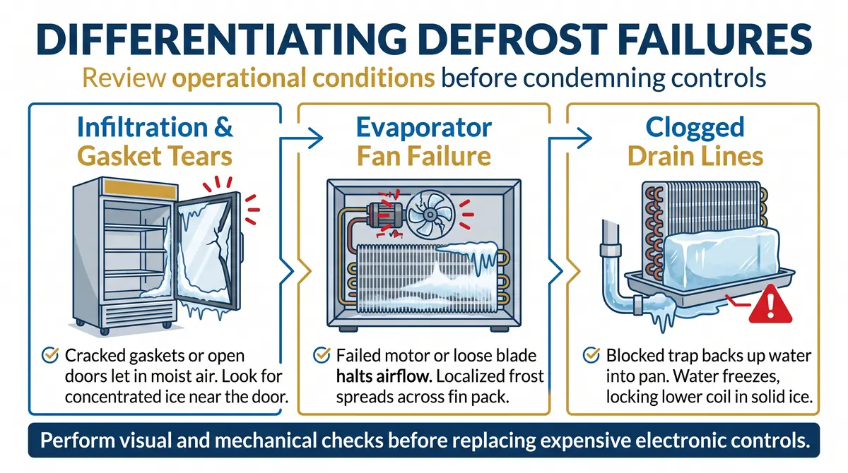
Differentiating Defrost Failures from Airflow & Load Issues
Not all frozen evaporator coils result from component breakdowns in the defrost circuit. Review operational conditions before condemning controls:
- Infiltration & Gasket Tears: Moist ambient air entering through cracked door gaskets, unsealed wall penetrations, or propped-open doors introduces moisture faster than scheduled defrost cycles can clear it. Look for concentrated ice buildup on the coil face closest to the door.
- Evaporator Fan Motor Failures: A failed evaporator fan motor or loose fan blade halts airflow across that section of the coil, causing localized frost accumulation that spreads across the fin pack.
- Clogged Drain Lines: An unheated or blocked condensate trap backs up water into the drain pan. During the subsequent freezing cycle, this water expands, locking the lower coil in solid ice.
Sourcing Reliable Defrost Components
Replacing failed refrigeration components demands exact physical and electrical cross-referencing:
- Bimetal Klixon Switches: Match the cut-in (fan delay) and cut-out (termination) temperature ratings, contact switching configuration, physical tube-clamping diameter (e.g., 3/8", 1/2", 5/8" OD), and lead wire insulation type.
- Defrost Heaters: Match voltage, total wattage, sheath length, and terminal configuration. Never bend rigid heating elements unless explicitly designed as field-formable components.
- Defrost Timers: Match clock motor voltage (120V vs. 208/240V, 50/60 Hz), switch contact ratings, cycle frequency capabilities, and terminal layout.
AllPoints offers a full OEM parts catalog alongside cost-effective OCM alternatives, giving technicians more options when sourcing compatible defrost controls, heaters, and refrigeration components.
Frequently Asked Questions
Why does a walk-in freezer coil keep freezing into a solid block of ice even though the heaters are working?
If electric heaters warm properly during defrost, the issue often stems from incomplete defrost termination, inadequate defrost duration, or a blocked condensate drain line. If the defrost cycle terminates too early, a residual core of ice remains inside the center of the coil. When refrigeration resumes, this core accumulates more frost each cycle until the entire coil is choked.
Can an open drain-line heater cause the entire evaporator coil to freeze?
Yes. In a low-temperature walk-in freezer, melted frost must exit the box before it drops below freezing. If the drain-pan or drain-line heater fails, meltwater freezes in the pan and backs up. Over several cycles, ice builds from the bottom rows upward until it blocks airflow through the entire evaporator fin pack.
How can technicians distinguish a defrost failure from a refrigerant issue?
Frost patterns can provide useful diagnostic clues. A coil covered in heavy, widespread ice often indicates inadequate defrost or restricted airflow, while uneven frost formation may point toward refrigerant feeding or system performance problems. However, visual inspection alone cannot confirm the cause. Technicians should evaluate airflow, operating pressures, superheat, and the defrost sequence before determining whether a refrigerant or control issue is responsible.
Find the Right Parts for Your Next Refrigeration Repair
Accurate defrost diagnostics help technicians identify failed components, prevent repeat service calls, and keep commercial refrigeration equipment operating reliably.
From defrost timers and heaters to termination thermostats and refrigeration controls, AllPoints provides access to a full OEM parts catalog alongside cost-effective OCM alternatives. Find the right replacement parts for your equipment, with fast nationwide shipping and support from experienced parts experts.