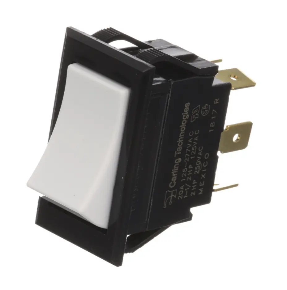
Understanding Electrical Load Ratings for Commercial Fryer Contactors and Switches
Sep 23rd 2026
Reading Time: 4 Minutes
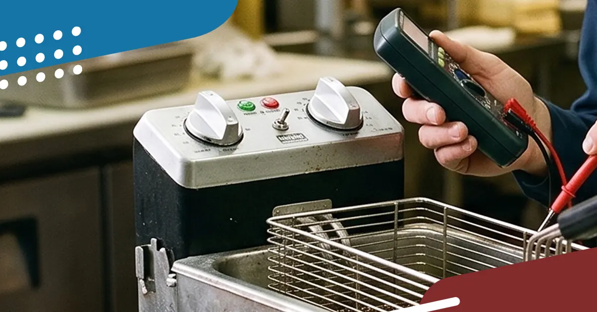
Summary
High-wattage commercial electric fryers place substantial electrical loads on the contactors and switches that control their heating circuits. Selecting a replacement contactor or power switch based solely on physical dimensions or coil voltage frequently leads to premature contact degradation, terminal overheating, or component failure.
Safe and reliable parts procurement requires matching resistive amperage ratings, operating voltage, pole configurations, and terminal requirements to the equipment manufacturer’s specifications. Sourcing properly cross-referenced Original Component Manufacturer (OCM) switching hardware offers cost savings while maintaining equipment reliability and safety.
Why Electrical Load Ratings Matter in Commercial Fryers
Commercial electric fryers are among the most energy-demanding appliances on the commercial cooking line. A multi-vat commercial fryer bank frequently operates on 208V, 240V, or 480V three-phase service, with heating element packages drawing substantial electrical power to maintain setpoint temperatures during high-volume cooking.Because cooking oil requires tight temperature regulation during rapid recovery cycles, element contactors repeatedly pull in and drop out during normal heating cycles. As the contacts make and break the circuit under load, electrical arcing naturally occurs across the contact faces.

If a replacement contactor or power switch is not rated for the specific resistive heating application, that electrical stress can result in:
- Contact Pitting & High Resistance: Causes localized overheating at the component terminals, risking damage to wire insulation and terminal blocks.
- Contact Welding: Contacts fuse closed, creating a runaway heating condition where the heating elements remain energized regardless of temperature control demand—forcing the system to rely entirely on the mechanical high-limit safety.
- Coil Failure: Excessive control circuit voltage drop or an improperly matched coil can cause chatter, accelerating contact wear and leading to coil burnout.
Key Electrical Ratings: Resistive vs. Inductive Loads
A common pitfall when sourcing replacement contactors is confusing motor load ratings (such as Full Load Amps / FLA or Horsepower) with Resistive Amperage ratings (often classified under standards like IEC AC-1 for non-inductive or slightly inductive heating loads).
- Inductive Loads (Motors and Compressors): Characterized by high inrush current upon startup, followed by lower continuous operating current. Sized primarily by FLA, Locked Rotor Amps (LRA), and Horsepower.
- Resistive Loads (Fryer Heating Elements): Characterized by steady-state current draw with minimal inrush spike, running near full load current throughout the heating cycle. Sized primarily by Resistive Amperes (Res. A), Kilowatts (kW), and operating voltage.
| Specification Parameter | What It Measures | Sourcing Requirement for Fryers |
|---|---|---|
| Resistive Amps / AC-1 Rating | Maximum current-carrying capacity for non-inductive or slightly inductive resistance heating circuits. | Must meet or exceed the circuit's calculated operating current at the specified voltage. |
| Full Load Amps (FLA) / Inductive Rating | Current-carrying capacity under continuous mechanical motor load. | Applicable when switching motors (e.g., built-in oil filtration pump motors), but not the basis for element circuits. |
| Coil Voltage & Frequency | The control circuit voltage and frequency required to pull in and hold the contactor armature (e.g., 24VAC, 120VAC, 208/240VAC; 50/60 Hz). | Must match the control transformer output and wiring diagram exactly. |
| Terminal Configuration | The physical connection style (e.g., box lugs, screw terminals, quick-connect tabs). | Must accommodate the specified conductor size, terminal type, and wire insulation temperature rating. |
Procurement Rule:Never select a heating-element contactor based only on its motor horsepower or FLA rating. Verify the manufacturer’s rating for the actual resistive heating application, operating voltage, and required current. For example, a 17 kW balanced resistive load operating at 208V three-phase draws approximately 47A per line—making a contactor rated below that operating current unsuitable for the application:
Amps = Watts ÷ (Volts × 1.732)
17,000 ÷ (208 × 1.732) ≈ 47.2A
⚠️ Safety & Handling Boundary
Commercial fryer electrical systems can contain hazardous line voltage even when equipment controls are switched off. Electrical diagnosis and component replacement should be performed only by qualified service personnel using the equipment manufacturer’s service procedures, wiring diagrams, and required Lockout/Tagout (LOTO) practices.
Sourcing Checklist: Contactors & High-Amp Switches
Before purchasing or approving replacement switching controls for commercial fryers, verify the following specifications against the equipment manual and engineering data plate:
1. Verify True Operating Amperage per Phase
Do not estimate current draw based on cabinet size. Use the rated kilowatt capacity and operating voltage from the data plate to confirm amperage per line. Select a contactor with the appropriate load rating for the calculated operating current, following the fryer manufacturer’s service documentation and the contactor manufacturer’s application requirements.

2. Match Pole Configuration & Auxiliary Contacts
- Poles: Match the original pole configuration and equipment wiring diagram. Many three-phase electric fryers use multi-pole contactors to switch their heating circuits, but configurations vary by model.
- Auxiliary Switches: Verify whether the original contactor includes integrated or snap-on auxiliary contacts (normally open or normally closed) used for control interlocks, indicator lights, or digital controller status inputs.
3. Review Conductor Terminations & Temperature Ratings
High operating currents generate significant heat at loose or improperly matched terminations:
- Verify that replacement terminals accommodate the conductor size, terminal type, and temperature rating specified by the equipment manufacturer.
- Never reduce conductor size or substitute a lower-temperature wire type.
4. Evaluate Power Switches & Environmental Protection
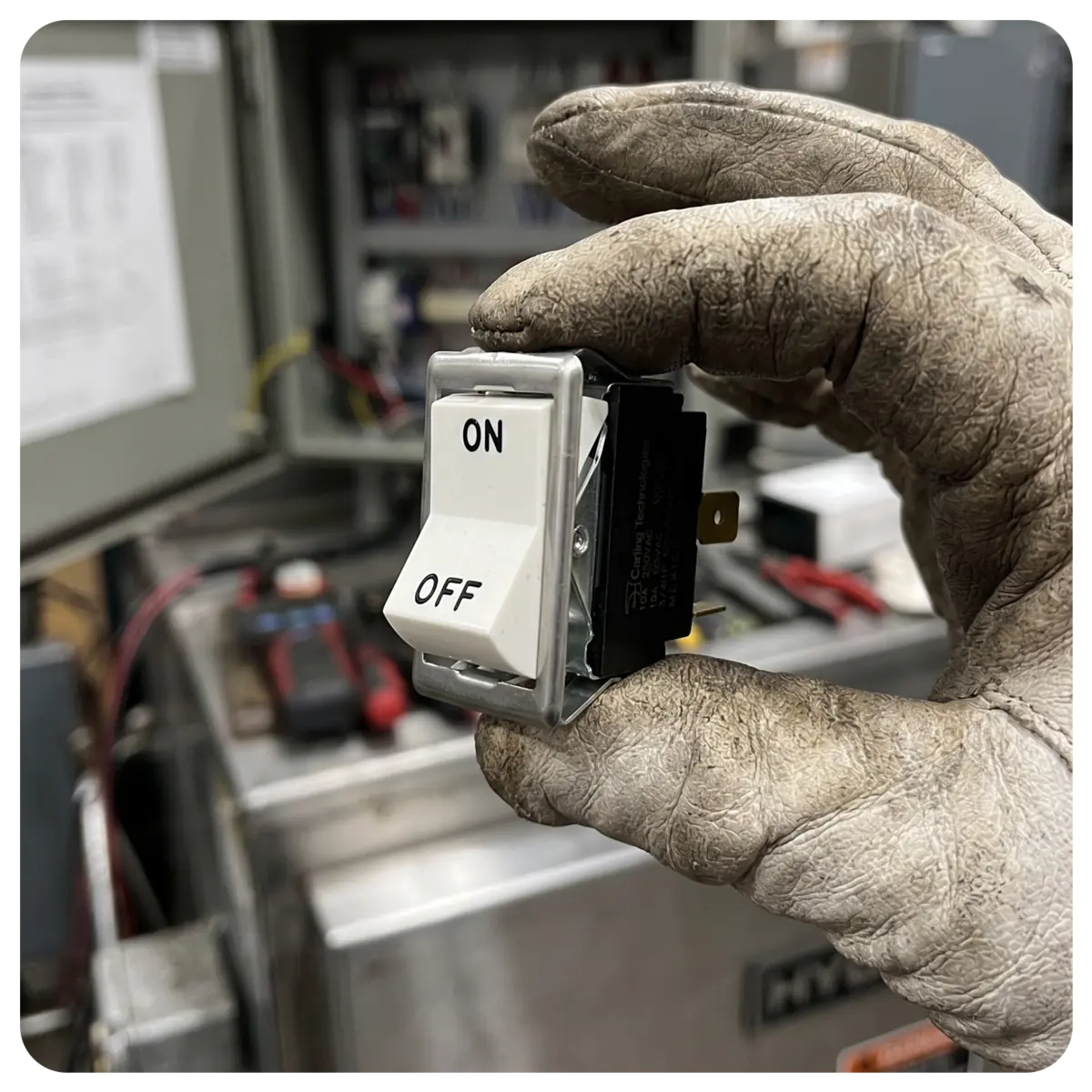
Master toggle or rocker switches controlling fryer power or filtration systems must be evaluated for:
- Load Rating: Ensure front-panel switches are rated for line-voltage interruption if they directly switch heavy loads rather than low-voltage pilot circuits.
- Environmental Protection: Fry lines expose components to grease, heat, and moisture. Where specified by the equipment manufacturer, use switches and protective boots with the appropriate environmental rating for the application.
Evaluating OCM Replacement Options
High-amp contactors and industrial switches used in commercial fryers are often sourced by equipment manufacturers from established electrical-component manufacturers. This creates opportunities to source compatible Original Component Manufacturer (OCM) components when the specifications and application requirements match.
When evaluating an OCM alternative, verify the coil voltage and frequency, load rating, pole configuration, terminal arrangement, mounting dimensions, environmental requirements, and applicable component certifications against the original part and equipment documentation:
- Direct Compatibility: Properly cross-referenced OCM alternatives are selected to meet the electrical and dimensional requirements of the intended application.
- Cost Efficiency: Properly cross-referenced OCM components can provide cost savings compared with OEM-packaged alternatives.
- Application Requirements: Verify all required approvals, certifications, and manufacturer specifications before installation.
Frequently Asked Questions
Why did a newly replaced fryer contactor weld closed prematurely?
Contact welding can result from an inadequate load rating, unstable coil voltage that causes contactor chatter, excessive switching wear, or other electrical or mechanical faults. Verify that the replacement contactor is correctly rated for the application and have a qualified technician diagnose the circuit before replacing a failed component.
Can I substitute a contactor with a different number of poles?
Not based on pole count alone. Verify the fryer’s wiring diagram and manufacturer specifications before changing contactor configurations. Coil voltage, load rating, contact arrangement, auxiliary contacts, mounting, and the way each conductor is switched must all match the requirements of the circuit. Fryer manufacturers provide model-specific wiring diagrams and service documentation for this reason.
What is the difference between a Definite Purpose (DP) contactor and an IEC contactor?
Definite Purpose and IEC contactors use different rating conventions and product designs. Either may be appropriate in equipment designed for it, but they should not be considered interchangeable based solely on amp rating. Verify the required utilization/load rating, coil characteristics, pole and auxiliary-contact configuration, mounting, terminals, operating environment, and equipment manufacturer specifications before selecting a replacement. IEC contactors commonly identify AC-1 ratings for non-inductive or slightly inductive loads, including resistance heating applications.
Keep Fryer Electrical Systems Running Reliably
Reduce unexpected fryer downtime by matching replacement contactors and switches to the electrical requirements of the equipment. Explore the AllPoints Parts Catalog or Technical Resources to find contactors, switches, terminals, high-temperature wiring, and other electrical components for commercial kitchen service and repair.