Diagnosing Commercial Fryer Ignition Faults: Millivolt vs. Electronic Systems
Sep 30th 2026
Reading Time: 4 Minutes

Summary
Commercial gas fryer ignition failures generally stem from either self-generating millivolt pilot circuits or line-voltage electronic ignition systems. Because each design uses fundamentally different electrical inputs, safety interlocks, and gas valve operators, misdiagnosing the root cause often leads to unnecessary gas valve or control board replacements. Service technicians can isolate ignition faults by:
- Differentiating closed-circuit thermopile voltage drop under load from open-circuit potential in millivolt systems.
- Verifying microamp flame-rectification signals and spark integrity before condemning electronic ignition modules.
- Checking dynamic gas supply and manifold pressures under full firing load before blaming electrical controls.
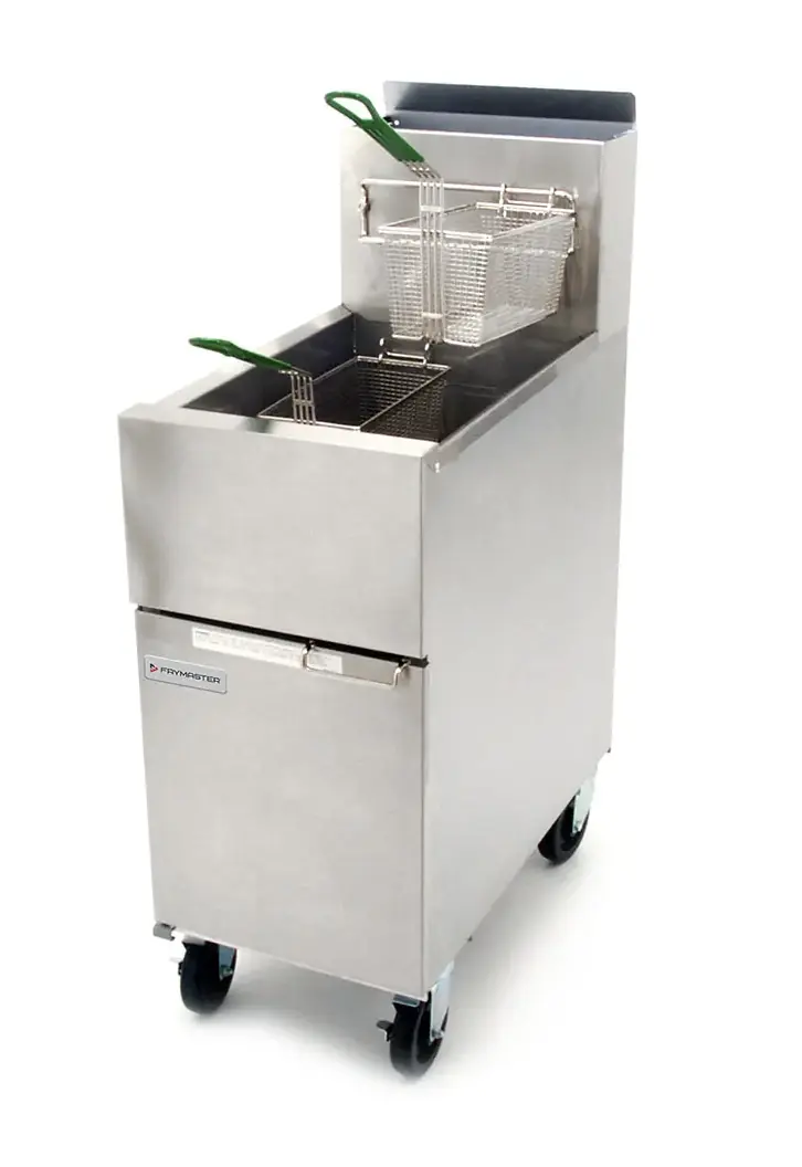
Millivolt vs. Electronic Ignition Architectures
Commercial gas fryers use two distinct ignition architectures. Identifying the system configuration from the equipment data plate and wiring schematic determines the proper diagnostic path.
| System Type | Power Source | Primary Flame / Pilot Safety | Main Gas Valve Operator | Common Failure Points |
|---|---|---|---|---|
| Millivolt (Standing Pilot) | Thermopile (powerpile) self-generated DC voltage (commonly 500 mV to 750 mV open circuit). | Thermocouple and/or thermopile, depending on gas-control design. | Millivolt gas-control operator powered by thermopile output. | Excessive resistance across high-limit safeties or thermostats, degraded thermopiles, oxidized wiring terminals, weak pilot flame. |
| Electronic (Direct Spark / Intermittent Pilot) | External line voltage (typically 120 VAC or 24 VAC via step-down transformer). | Flame rectification rod generating a low DC microamp ($\mu\text{A}$) signal through the ionized flame to ground. | Line-voltage or 24 VAC dual-solenoid combination gas valve. | Poor chassis grounding, carbon buildup on flame sense rods, cracked ceramic spark insulators, failed ignition control modules. |
⚠️ Safety & Energy Control Boundary
Commercial gas equipment presents simultaneous fuel gas and electrical hazards. Diagnostic procedures involving energized electrical circuits, live gas pressure, or combustion testing should be performed only by qualified commercial foodservice equipment technicians in accordance with the equipment manufacturer's service instructions and applicable codes. Before servicing gas-train components, verify that the manual gas shutoff valve is closed and follow OSHA Lockout/Tagout procedures for any line-voltage connections. Ensure kitchen exhaust ventilation is active throughout live testing to prevent the accumulation of unburned fuel gas or combustion byproducts.
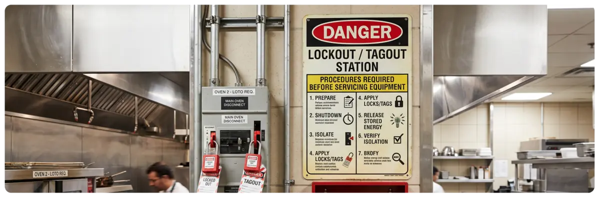
Diagnosing Millivolt Ignition Circuits
Millivolt systems are self-contained and require no external electrical utility to operate the gas valve. However, because the circuit operates on direct-current fractions of a volt, excessive resistance in the loop can prevent the main gas valve from pulling in.
Millivolt Series Loop: Thermopile → High-Limit Safety → Operating Thermostat → Gas Valve Operator → Return
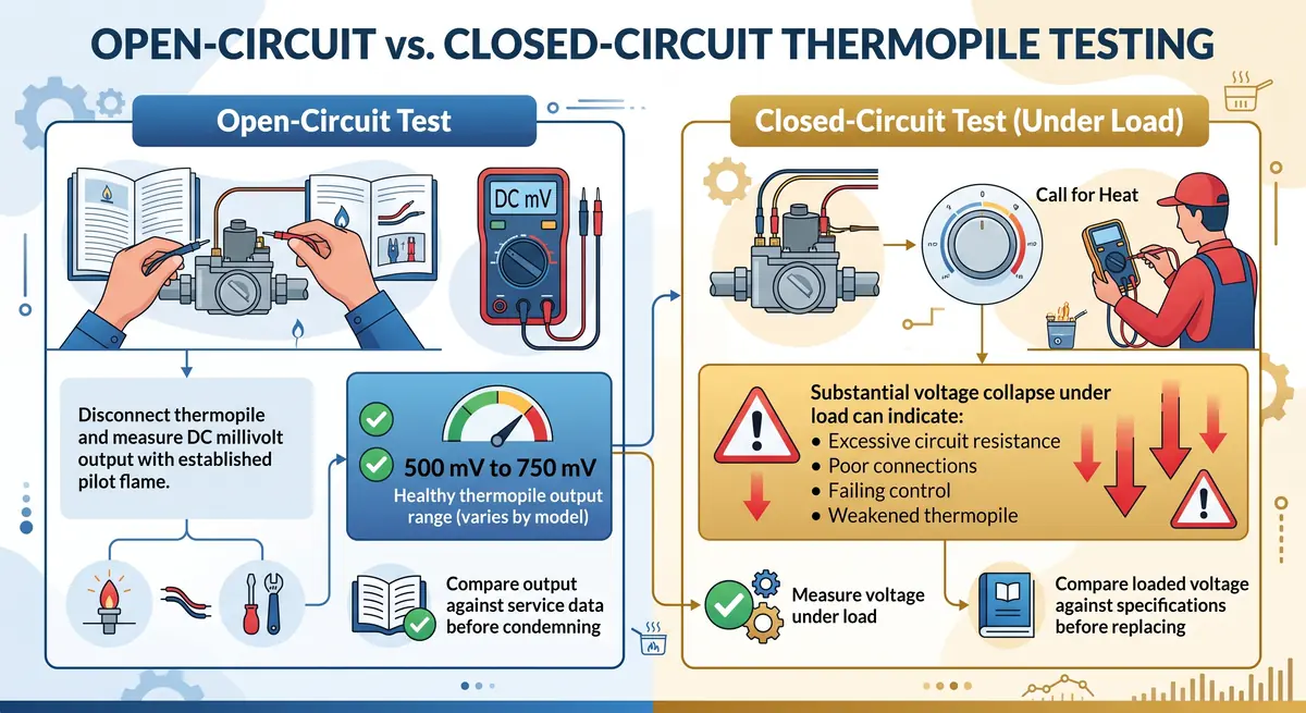
Open-Circuit vs. Closed-Circuit Thermopile Testing
Open-Circuit Test: Disconnect the thermopile according to the manufacturer’s service procedure and measure DC millivolt output with a properly established pilot flame. Healthy thermopile output commonly falls within the 500 mV to 750 mV range, although specifications vary by component and fryer model. Compare the measured output against the manufacturer’s service data before condemning the thermopile.
Closed-Circuit Test (Under Load): Reconnect the thermopile leads to the valve terminals and place the operating thermostat into a call for heat. Measure voltage across the terminals under load. A substantial voltage collapse under load can indicate excessive circuit resistance, poor connections, a failing control, or a weakened thermopile. Compare loaded voltage against the fryer and gas-valve manufacturer's specifications before replacing a component.
Voltage Drop Across Safety & Operating Controls
If open-circuit voltage is within specification but loaded voltage drops below operating thresholds, isolate unwanted resistance across each series safety device:
- Measure the voltage drop across each closed safety and operating control while the system is calling for heat.
- Excessive voltage drop across an individual control or terminal connection identifies the source of unwanted resistance.
- Compare all measurements with manufacturer service specifications before replacing components.
- Inspect and clean all spade connectors. Even a light film of cooking grease or terminal oxidation can introduce enough resistance to disrupt a millivolt signal.
Diagnosing Electronic Spark & Flame-Sense Systems
Electronic fryer ignition systems use an ignition module or control board to manage the ignition sequence, spark generation, gas-valve operation, and flame verification.
1. The Pre-Ignition & Spark Sequence
When the operating thermostat calls for heat:
Control Power: Confirm rated supply voltage (typically 24 VAC or 120 VAC) is present at the ignition module input terminals.
Trial for Ignition: Inspect the high-voltage spark cable and ceramic insulator for cracks, carbon tracking, or grease contamination. Verify that the spark is crossing the electrode gap specified by the equipment manufacturer rather than arcing to the burner bracket or another grounded surface.
Valve Voltage: During the trial-for-ignition window, confirm that the module outputs the rated voltage to the pilot or main valve solenoid.
2. Flame Rectification Diagnostics
Most electronic fryers utilize flame rectification to confirm burner presence. The alternating current (AC) applied to the flame rod is rectified by the ionized gas flame into a small direct current (DC) signal returning through the burner chassis to ground.
Measure Flame Signal: Place a digital multimeter in series with the flame sensor lead, set to DC microamps (μA).
Evaluate Current: Flame-signal current is commonly measured in low DC microamps (typically 1.0 μA to 5.0 μA), with acceptable values and lockout thresholds varying by ignition module. Compare the measured signal with the module manufacturer's service specification.
Isolate Signal Loss Causes:
- Contaminated Flame Rod: Remove carbon or oxidation using an appropriate nonconductive abrasive recommended by the component manufacturer, taking care not to damage the rod or ceramic insulator.
- Burner Ground Reference: Ensure the burner assembly has a clean, metal-to-metal bonding connection to the fryer chassis. Corrosion or loose mounting hardware can disrupt the ground return path.
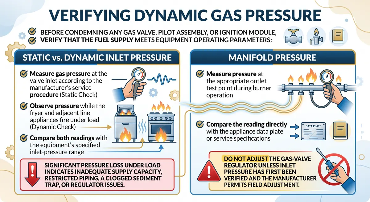
Verifying Dynamic Gas Pressure
Before condemning any gas valve, pilot assembly, or ignition module, verify that the fuel supply meets equipment operating parameters:
Static vs. Dynamic Inlet Pressure: Measure gas pressure at the valve inlet according to the manufacturer's service procedure, then observe pressure while the fryer and adjacent line appliances fire under load. Compare both readings with the equipment's specified inlet-pressure range. Significant pressure loss under load indicates inadequate supply capacity, restricted piping, a clogged sediment trap, or regulator issues.
Manifold Pressure: Measure pressure at the appropriate outlet test point during burner operation and compare the reading directly with the appliance data plate or service specifications. Do not adjust the gas-valve regulator unless inlet pressure has first been verified and the manufacturer permits field adjustment.
Sourcing Field-Ready Fryer Replacement Parts
Ignition repairs on commercial fryers demand exact mechanical, electrical, and gas-train alignment:
- Gas Valve Sourcing: Verify whether the replacement valve is single-stage or two-stage, match pipe connection sizes (typically 1/2" or 3/4" NPT), confirm coil operating voltage, and ensure it is designated for the correct fuel type (Natural Gas vs. LP).
- High-Limit Thermostats: Never bypass or alter a safety high-limit switch. Always source exact temperature-rated capillary cutouts with matching bulb diameters and stuffing-box threads.
- OCM Components: Many gas valves, thermopiles, thermocouples, and pilot components are produced by established gas-control manufacturers such as Robertshaw, Resideo, and BASO. Where compatible Original Component Manufacturer (OCM) options are available, technicians can source components that meet the required application specifications while potentially reducing parts acquisition costs.
Frequently Asked Questions
Why does a millivolt fryer pilot stay lit when holding the knob, but drops out immediately when released?
This symptom commonly points to an insufficient pilot-safety signal, poor flame impingement on the sensing element, a weak thermocouple or thermopile, or a problem within the gas-control safety mechanism. Inspect the pilot flame size and shape, verify that the pilot orifice is clear of debris or lint, and test the sensor output according to the manufacturer's service procedure before replacing the valve or sensor.
Can an electronic ignition fryer fail if the polarity of the electrical supply is reversed?
Yes. Many electronic flame-rectification modules are phase-sensitive and require a direct line-to-neutral reference to complete the microamp flame circuit to ground. Reversing polarity on standard 120V plug-in fryers can cause the burner to light during the trial for ignition and then lock out immediately because the module cannot verify the flame current.
What is the difference between a thermocouple and a thermopile?
A thermocouple consists of two dissimilar metals joined at a sensing junction, producing a small DC voltage (commonly 25 mV to 35 mV) used primarily to hold a pilot safety valve open. A thermopile (or powerpile) combines multiple thermocouples in series inside a single probe, generating higher voltage (commonly 500 mV to 750 mV) sufficient to power both the pilot safety mechanism and the main gas valve operator coil in self-powered millivolt systems.
Keep Fryer Lines Firing Reliably
Accurate diagnosis of commercial fryer ignition circuits reduces troubleshooting time and helps prevent premature component replacement. Use the AllPoints Parts Catalog and Technical Guides to cross-reference compatible combination gas valves, millivolt thermopiles, ignition modules, and high-limit cutouts by equipment model and serial number.